Herramientas
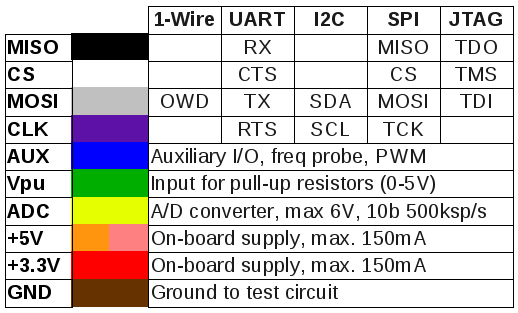
Bus Pirate
Enlaces
Referencia
1 2 3 4 5 6 7 8 9 10 11 12 13 14 15 16 17 18 19 20 21 22 23 | |
Conexión
1 | |
Adaptador USB-UART (modo bridge)
Bus Pirate se puede utilizar como un adaptador USB-UART configurándolo en modo UART y activar el macro de modo transparente. Para ello seguir la siguiente secuencia:
1 2 3 4 5 6 7 8 9 10 11 12 13 14 15 16 17 18 19 20 21 22 23 24 25 26 27 28 29 30 31 32 33 34 35 36 37 38 39 40 41 42 43 | |
Adaptador USB-UART (modo debug)
Cuando utilizamos el modo UART en modo debug, tal y como se describe aquí, sólo tenemos un buffer de 4 bytes, por lo que es fácil obtener un overrun del mismo. En ese caso, al leer (comando r) se nos mostrará el error:
1 | |
En esas situaciones usar el modo transparente o usar el comando 'start' ([).
Logic Analizer
Enlaces
- sigrok: Portable, cross-platform, Free/Libre/Open-Source signal analysis software suite that supports various device types (e.g. logic analyzers, oscilloscopes, and many more).
- Getting started with a logic analyzer
- Using the USB Logic Analyzer with sigrok PulseView
M328 Transistor Tester
Enlaces
- 2016 DIY KITS ATMEAG328P M328 Transistor Tester LCR Diode Capacitance ESR meter PWM Square wave Signal Generator with case: ~12€
- M328 Transistor Tester manual
Enumeración funciones
Firmware 1.12k
- Transistor: Medidor de transistores.
- Frecuency: Medidor de frecuencias. Conectar las puntas en la entrada PWM (superior).
- f-Generator: Generador de frecuencias. Conectar las puntas en la salida PWM (inferior).
- 10-bit PWM: Generador de señal PWM. Conectar las puntas en la salida PWM (inferior).
- C+ESR@TP1:3: Capacímetro con posibilidad de medir en placa ya que genera tensiones de ~300mV. Aunque es recomendable medir antes con un osciloscópio si es así (mi unidad aplicaba 5V igual que el capacímetro normal). Conectar un par de puntas en las entradas 1 y 3.
- Medidor de inductancias:
- Capacímetro: No sirve para medir en placa ya que genera tensiones de 5V. Descargar los condensadores antes de aplicarlos al medidor.
- DS18B20:
- C(uF)-correction: Calibración del capacímetro.
- IR_Decoder: Implementa un par de protocolos de transmisión de datos por infrarrojos. Hay que conectar un receptor IR en las entradas 1, 2 y 3.
- IR_Encoder: Implementa un par de protocolos de transmisión de datos por infrarrojos. Hay que conectar un LED emisor de IR en la salida PWM (inferior).
- DHT11:
- Selftest: Calibración del tester.
- Voltage: Voltímetro. Conectar las puntas en la entrada de voltímetro (inferior).
- FrontColor: Color RGB de los caracteres.
- BackColor: Color RGB del fondo.
- Show data: Muestra los datos de calibración y el juego de gráficos y caracteres.
- Switch off: Apagado.
Firmware
El repositorio SVN del proyecto se baja con:
1 | |
Para actualizarlo a la última versión una vez bajado, ejecutar desde el propio directorio:
1 | |
También se puede explorar el repositorio en esta URL.
La configuración del modelo enlazado arriba es la mega328_color_kit.
Instrucciones sobre la carga del firmware en este hilo del foro EEVBlog.
MiniPRO TL866xx
Enlaces
- XGecu T56 Universal programmer
- minipro: An open source program for controlling the MiniPRO TL866xx series of chip programmers. Instalación en Linux
Firmware
- Descargar el último paquete del fabricante desde este enlace, que incluye la utilidad de interfaz de usuario para Windows y el fichero
.datcon el firmware. - Descomprimir el .exe que lleva dentro. Ese exe a su vez es un paquete autodescomprimible, por lo que se puede abrir con un descompresor como WinRAR o el Gestor de archivadores de Linux. Extraer de él el fichero
updateII.dat. Por algún motivo da error con el Gestor de archivadores de Linux. Se puede descomprimir con Archive Extractor Online. -
Flashear el fichero
updateII.datcon la utilidad minipro:1 2 3 4 5 6 7 8 9 10 11 12 13
edumoreno@eduardo-HP-Folio-13:~$ minipro -F updateII.dat
Found TL866II+ 04.2.86 (0x256)
Warning: Firmware is out of date.
  Expected  04.2.123 (0x27b)
  Found     04.2.86 (0x256)
updateII.dat contains firmware version 4.2.125 (newer)

Do you want to continue with firmware update? y/n:y
Switching to bootloader... OK
Erasing... OK
Reflashing... 100%
Resetting device... OK
Reflash... OK
Uso de utilidad minipro de linea de comando
- Versión firmware y utilidad:
minipro -V - Testeo dispositivo:
minipro -t - Búsqueda de integrados compatibles:
minipro -L <search> - Indicar modelo de programador
TL866II+en comandos:minipro -q tl866ii - Programar integrado (ejemplo con ATTiny85):
minipro -p ATTINY85 -w <filename> - Leer integrado (ejemplo con ATTiny85; además del volcado de la flash, genera un par de ficheros adicionales, uno con el volcado de la EEPROM y otro con la configuración de fuse bits):
minipro -p ATTINY85 -r <filename> - Leer tipo de memoria concreta (posibles valores: code, data, config) en integrado (ejemplo con ATTiny855):
minipro -p ATTINY85 -r <filename> -c <type>
Pinecil
Enlaces
- Carcasas transporte
- Firmware
Menu cheatsheet
Correspondiente a IronOS v2.16:
- Soldering mode
+short press: Short temperature increment+long press: Long temperature increment-short press: Short temperature decrement-long press: Long temperature decrement+/-same time press: Exit soldering mode-long press: Exit soldering mode+long press: Boost mode (if enabled)
- Power settings
- Power source: Sets cutoff voltage. (DC 10V) (S 3.3V per cell, disable power limit) # Default: DC
- QC voltage: Max QC voltage the iron should negotiate for # Default: 9.0
- PD timeout: PD negotiation timeout in 100ms steps for compatibility with some QC chargers # Default: 20
- Soldering settings
- Boost temp: Temperature used in "boost mode" # Default: 420
- Heat on power up: O=off | S=soldering temp | Z=standby at sleep temp until moved | R=standby without heating until moved # Default: O
- Temp change short: Temperature-change-increment on short button press # Default: 1
- Temp change long: Temperature-change-increment on long button press # Default: 10
- Allow locking buttons: While soldering, hold down both buttons to toggle locking them (D=disable | B=boost mode only | F=full locking) # Default: D
- Sleep mode
- Motion sensitivity: 0=off | 1=least sensitive | ... | 9=most sensitive # Default: 7
- Sleep temp: Tip temperature while in "sleep mode" # Default: 150
- Sleep timeout: Interval before \"sleep mode\" kicks in (S=seconds | M=minutes) # Default: 50S
- Shutdown timeout: Interval before the iron shuts down (M=minutes) # Default: 10M
- Hall sensor sensitivity: Sensitivity of the Hall effect sensor to detect sleep (O=off | L=low | M=medium | H=high) # Default: L
- User interface
- Temperature unit: C=Celsius | F=Fahrenheit # Default: C
- Display orientation: R=right-handed | L=left-handed | A=automatic # Default: R
- Cooldown blink: Flash the temperature reading after heating was halted while the tip is still hot # Default: False
- Scrolling speed: Speed info text scrolls past at (S=slow | F=fast) # Default: S
- Reverse + - keys: Reverse assignment of buttons for temperature adjustment # Default: False
- Anim. speed: Pace of icon animations in menu (O=off | S=slow | M=medium | F=fast) # Default: M
- Anim. loop: Loop icon animations in main menu # Default: True
- Brightness: Adjust the brightness of the OLED screen # Default: 4
- Invert: Invert the colours of the OLED screen # Default: False
- Detailed idle screen: Display detailed information in a smaller font on the idle screen # Default: False
- Detailed solder screen: Display detailed information in a smaller font on soldering screen # Default: False
- Advanced settings
- Power limit: Maximum power the iron can use (W=watt) # Default: Off
- Factory reset?: Reset settings to default
- Calibrate temperature?: Start tip temperature offset calibration
- Calibrate input voltage?: Start VIN calibration (long press to exit)
- Power pulse: Intensity of power of keep-awake-pulse (watt) # Default: Off