Módulos
SI5351 Clock Generator
Generador de señal de reloj entre 8KHz y 160MHz configurable por I2C. Compatible con 5V y 3.3V. Los niveles de señal se adecúan al de alimentación, por tanto para utilizar la misma tensión de alimentación que luego queremos que se utilice en la comunicación I2C. El reloj de salida es de 3V.
Enlaces
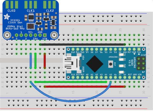
Conexión
Programación
- Bajar librería Adafruit_Si5351_Library.
- Volcar todo su contenido a un directorio llamado
Adafruit_Si5351.
- Copiar el directorio anterior a
arduinosketchfolder/libraries/.
- Reiniciar el IDE.
Una vez preparado el entorno cargar un programa como el siguiente:
 1
 2
 3
 4
 5
 6
 7
 8
 9
10
11
12
13
14
15
16
17
18
19
20
21
22
23
24
25
26
27
28
29
30
31
32
33
34
35
36
37
38 | #include <Adafruit_SI5351.h>
#include <errors.h>
#include <asserts.h>
#include <Wire.h>
Adafruit_SI5351 clockgen = Adafruit_SI5351();
void setup(void) {
if (clockgen.begin() != ERROR_NONE) {
// There was a problem detecting the IC ... check your connections
while(1);
}
// INTEGER ONLY MODE --> most accurate output
// Setup PLLA to integer only mode @ 900MHz (must be 600..900MHz)
// Set Multisynth 0 to 112.5MHz using integer only mode (div by 4/6/8)
// 25MHz * 36 = 900 MHz, then 900 MHz / 8 = 112.5 MHz
clockgen.setupPLLInt(SI5351_PLL_A, 36);
clockgen.setupMultisynthInt(0, SI5351_PLL_A, SI5351_MULTISYNTH_DIV_8);
// FRACTIONAL MODE --> More flexible but introduce clock jitter
// Setup PLLB to fractional mode @616.66667MHz (XTAL * (24+2/3))
// Setup Multisynth 1 to 13.55311MHz (PLLB/(45+1/2))
clockgen.setupPLL(SI5351_PLL_B, 24, 2, 3);
clockgen.setupMultisynth(1, SI5351_PLL_B, 45, 1, 2);
// Multisynth 2 is not yet used and won't be enabled, but can be
// Use PLLB @ 616.66667MHz, then divide by (900+0/1) -> 685.185 KHz
// then divide by 64 for 10.706 KHz
// configured using either PLL in either integer or fractional mode
clockgen.setupMultisynth(2, SI5351_PLL_B, 900, 0, 1);
clockgen.setupRdiv(2, SI5351_R_DIV_64);
clockgen.enableOutputs(true);
}
void loop(void) {
}
|
A continuación vemos algunos ejemplos.
8MHz
| clockgen.setupPLL(SI5351_PLL_A, 24, 0, 1);
clockgen.setupMultisynth(0, SI5351_PLL_A, 75, 0, 1);
|
1MHz
| clockgen.setupPLL(SI5351_PLL_A, 24, 0, 1);
clockgen.setupMultisynth(0, SI5351_PLL_A, 75, 0, 1);
clockgen.setupRdiv(0, SI5351_R_DIV_8);
|
ATtiny high voltage programmer
Enlaces
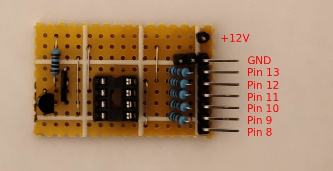
Montaje
Esquemático y montaje sobre stripboad hecho con Fritzing.
Conexión
La conexión del módulo a un Arduino UNO es como sigue:
Programación
El programa a cargar en el Arduino UNO es éste.
Abrir el puerto serie de Arduino a 19200 baudios y seguir las indicaciones que aparecen en consola.
Digispark
Enlaces